The main objective of this project is to develop a traction control system that detects the slipping of vehicle’s wheel and adjusts the velocity of the wheel accordingly. Nowadays, Robotic vehicles are becoming very complex and they require high levels of movement control. When the wheels of a vehicle begin to slip, this project will adjust the velocity of wheels. So that, the vehicle will move in the appropriate direction and reach its destination. Applications include remote controlled cars, vehicles traveling over rough terrain and exploratory robots.
By using speed sensors, anti-lock brakes, and microcontrollers, an electronic limited slip differential system will control the rotational velocity of the output shafts of a vehicle. By monitoring the wheel slipping, the microcontroller can activate the anti-lock brakes to slow down the wheel that is moving in high speed. An electronic system can adjust for different applications or conditions such as slippery weather, driving at different speeds or on and off-road terrain. This facility makes electronic system more useful than the mechanical system. Today, the dynamics of modern day traction control systems are becoming very complex. The basic idea motivated this project. The applications for this design are universal and very practical. By using this traction control system, Any vehicle with two or more wheels gets more stability and movement control. The feedback loop is the main component of this traction control system. It adjusts the velocity of each individual wheel to the velocity of the slowest wheel on the vehicle. It has both positive and negative feedback by speeding up the slowest wheel and slowing down the fastest wheel motor. The main purpose of this project is to develop a four wheel drive robot that controls the rotational velocity of each wheel and reduces the amount of slip when the vehicle is accelerating.
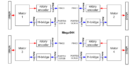
In this system, Mega644 microcontroller generates four PWM signals to be sent to the H-Bridges and to read the rotary encoder signals. In the below diagram, mechanical connections are shown in red and electrical connections are shown in blue. Inputs to the microcontroller are labelled as PINxn and outputs are labelled as PORTxn. OCRnx are the PWM output registers. They are used to control the motor speed.
The main components of this project are given below:
1. ATmega644
The Atmel Mega644 is used to adjust and control the velocity and acceleration of a vehicle. Four standard I/O pins, 4 PWM output pins, One 8-bit timer and one Analogue to Digital converter are the main features of the Mega644. The Mega644 chip builds a prototype board provided Prayog Labs. It features an easy way to power, connect to a RS232 interface, program the Atmel chip and attach a crystal clock.
2. Encoder Hardware and Measurement Software
3. Motor Control Softwares
4. Hyper term/ Debugging Code
5. PWM Control Code
6. PC Board Fabrication
7. H-bridge Hardware
8. Robot Chassis Frame Extension
9. Compiling Hardware Components Together
10. Debugging
11. Final Report


